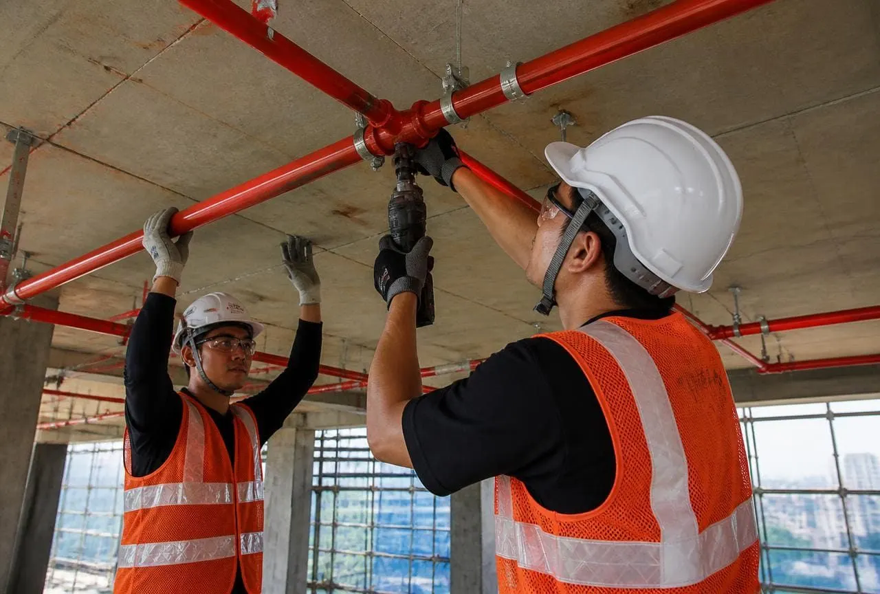
A fire hydrant system is the part of your fire protection that a fire service crew will actually use. Sprinklers and detectors act on their own; the hydrant system is manual, and it has to deliver water at usable pressure to the point where a person is standing with a hose, in a building that may already be full of smoke.
That means the individual components matter less than whether they work together — the tank feeds the pump, the pump holds the riser, the riser feeds the landing valve, and the landing valve delivers something a firefighter can control. Most failures we find on survey are failures of that chain, not of a single item.
The components, in the order water travels
1. Static water storage
A dedicated fire water tank — underground, at terrace level, or both — reserved for firefighting and not drawn down by domestic use. The reserved volume is set by the occupancy, building height and the system's design duration, so it is defined by the applicable standard for your building rather than by a single universal number.
The two things to check are simple: is the fire reserve actually protected from domestic draw-off, and does the level indication work? A tank with a stuck float or a jammed level switch is one of the most common reasons a pump does not start when it should.
2. The pump set
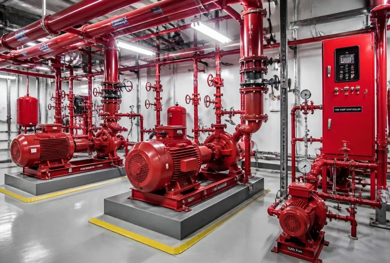
A conventional hydrant pump room contains three pumps, and each one has a distinct job:
- Jockey pump — a small, high-head, low-flow pump whose only purpose is to make up minor pressure losses so the system sits at standby pressure. If the jockey is running frequently, you have a leak, not a healthy system.
- Main pump (electric) — the duty firefighting pump, sized to deliver the design flow at the design head. It starts on a pressure drop that the jockey cannot recover.
- Standby pump (diesel engine driven) — takes over if mains power fails or the electric pump does not start. Its batteries, fuel level and cooling arrangement need checking as diligently as the pump itself.
Suction condition matters more than most people expect. A flooded suction — where the tank water level sits above the pump — is far more forgiving than a suction lift arrangement, which depends on a foot valve holding prime. If your pumps are on suction lift, priming is a permanent maintenance item.
3. Pressure control and starting logic
Pressure switches, a pressure gauge and, in most designs, an air vessel decide when each pump starts. The starting pressures are staged so the jockey runs first, then the electric main pump, then the diesel standby, each at a progressively lower pressure. Pumps are normally arranged to start automatically and stop manually, so a running fire pump does not shut itself down while a hose is still in use.
4. Risers and mains
The ring main or yard hydrant network distributes water at ground level; the wet riser carries it vertically. In a wet riser the pipe is kept full and pressurised at all times. A dry riser stays empty and is charged by a fire service pumping appliance through an inlet connection at ground level — an arrangement used where freezing or building type makes a permanently charged riser unsuitable.
Isolation valves on the network are the classic hidden failure. A valve closed during maintenance and never reopened will silently disconnect an entire section. Valves that are meant to be open should be locked or strapped open, and their position should be a checklist item on every inspection.
5. Landing valves, hose reels and cabinets
- Landing valve (hydrant valve) — the outlet at each floor or yard point, with an instantaneous coupling for the fire service hose. Single or double headed depending on the design.
- Hose box — canvas or RRL hose lengths and a branch pipe or nozzle, stored so they can be run out quickly rather than unpacked.
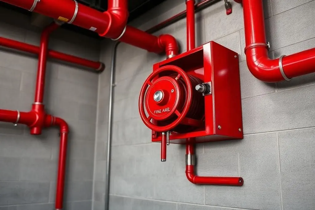
- First-aid hose reel — a semi-rigid small-bore hose on a swinging drum, intended for building occupants to use on a small fire before it grows. It is fed from the same riser.
- Fire brigade / breeching inlet — the ground level connection that lets a fire appliance pump into the riser, boosting or replacing the building's own supply.
The tests that prove the system works
A hydrant system is one of the few building systems you can genuinely prove. These are the checks that produce evidence rather than opinion.
| Test | What it proves | Typical frequency |
|---|---|---|
| Hydrostatic pressure test | Pipework, joints and fittings hold pressure without leaking | At installation, and after any major modification |
| Pump automatic start test | Each pump starts at its set pressure, in the correct sequence | Routine — commonly monthly |
| Diesel engine run test | Engine starts on battery, runs under load, cooling and fuel systems work | Routine — commonly weekly or monthly, under an AMC schedule |
| Flow and pressure test at the remote outlet | The design flow is actually available at the worst-case landing valve | Periodically, and after any network change |
| Valve position and operation check | Isolation valves are open, accessible and free to operate | Every routine inspection |
| Hose and hose reel check | Hoses are present, undamaged, correctly coupled and run out freely | Every routine inspection |
| Tank level and make-up check | Fire reserve is intact and the level device is working | Every routine inspection |
Two of these deserve emphasis. The flow test at the most remote outlet is the only test that proves hydraulic adequacy end to end — a pump can pass its own start test and still fail to deliver at the top of the riser if a valve is throttled or the network has been modified. And the diesel run test is the one most commonly skipped, which is exactly why diesel standby pumps are the component we most often find non-functional on first survey.
What goes wrong on real sites
- 1The jockey pump cycles every few minutes. This is a leak somewhere in the network — often a passing landing valve or a weeping joint — and it wears out the jockey while masking the real problem.
- 2The diesel pump will not start. Flat or sulphated batteries, no fuel, a closed fuel cock, or a battery charger that has been off for months.
- 3A section valve is closed. Frequently found during a flow test, when an entire wing produces no pressure.
- 4Hose boxes are empty or used as storage. Hoses go missing, get repurposed, or are found perished and split when run out.
- 5Landing valves are seized. Never operated, painted over, or with the outlet cap welded on by corrosion.
- 6Tank fire reserve has been drawn down. Domestic and fire supplies share a tank without a proper draw-off arrangement.
- 7Pressure gauges read zero or are broken. Nobody notices because nobody reads them.
None of these are exotic engineering failures. They are maintenance failures, and every one of them is caught by a scheduled inspection regime. If your building does not have one, that is the single highest-value thing to fix — our AMC Services and Fire Hydrant Systems pages set out what a routine covers.
What to ask a hydrant contractor
- Show me the hydraulic calculation for this network — flow and residual pressure at the most remote outlet, not just at the pump.
- What is the pump starting sequence, and what pressures are the switches set to?
- Is the suction flooded or lift? If lift, what keeps the pumps primed?
- How is the fire reserve protected from domestic draw-off?
- Where are the isolation valves, and how are they secured in the open position?
- What test records will I receive at handover — hydrostatic test, pump curves, flow test at the remote outlet, commissioning checklist?
- What does the maintenance schedule look like for year one, and what is tested weekly, monthly and annually?
A contractor who can answer those seven questions without hesitation is running a proper hydraulic design. A contractor who talks only about pipe sizes and pump horsepower is selling components, not a system.